PRE-CONSTRUCTION BIM
Design Engineering
We are providing our plumbing |hydraulic Engineering & BIM services globally to our customers from owner, architect, consulting engineers, design build contractor, general contractors, sub- contractors including facility management team. We have design standard & guidelines used for plumbing engineering design.
| USA | IPC, ASPE |
| CANADA | CSA B 137, CSA S 503, IPC, ASPE, |
| AUSTRALIA | NEW ZEALAND | AS/NZS 3500, NCC |
| UNITED KINGDOM | IRELAND | EUROPE | BS EN 806, BS EN 752, BS EN 12056 |
| SINGAPORE | MALAYSIA | SEA | SS 636, MS 1228, IPC |
| UAE | SAUDI | QATAR | GULF | DBC, SBC, QCS, IPC, ASPE |
| INDIA | NBC, SP 35 |
Offer Services
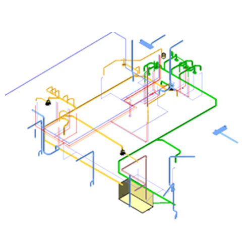
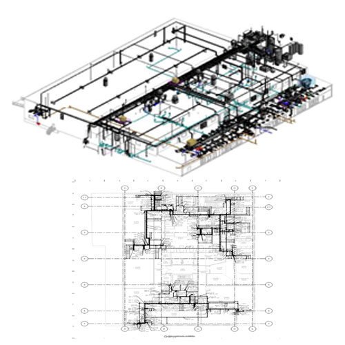
Design 3D Model (LOD 300)
We are specialize to develop design 3D models of plumbing | hydraulic network drainage, vent and water supply systems piping, fitting including all valves & accessories with all associated equipment and fixtures. We produce 3D Models based on the design Mark-ups, reference design drawing, samples provided by the client.
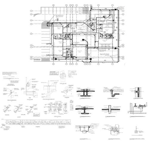
Design | Tender | Contract Drawing
Based on the mark-ups, reference drawing, we produce the design drawing for MEP system and work out the detail branch duct, pipe sizes as per the schematic and produce the complete design drawings /Tender Drawing or Construction drawing.
Design drawing set will have following list of drawings
CONSTRUCTION BIM
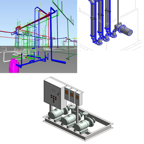
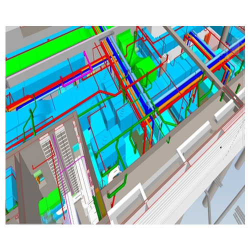
Construction 3D Model (LOD 350 | 400)
We are specialize in the virtual construction of 3D models @ LOD 400 of plumbing | Hydraulic systems i.e. drainage, water supply, gas, condensate drain piping with fitting including all valves & accessories with all associated equipment’s and fixtures.
We produce 3D Models based on contract drawings, technical specifications, and manufacturer details & client standards to complete the construction model.
Equipment Modeling
From the manufacturer’s 2D drawings and inline with Plumbing schedules, we create a 3D model of all the Plumbing equipment such as Plumbing Fixture, Pupms, Valves with all accessories for plumbing systems.BIM Co-Ordination
We generate a coordinated BIM model after resolving the clashes among all disciplines – Architectural, Structural, Concrete, Mechanical, Electrical, Plumbing, Fire Protection, etc.
First we identify the clash and create a view points level wise or Zone wise as per schedule and working on resolution internally. If we found any critical clash, we use to generate report and to co-ordinate with the all stakeholders and providing optimize solution to complete. Once all the clashes has been resolved, we make the final model for next stage to produce the shop drawing and As built drawing.
BIM DRAWINGS
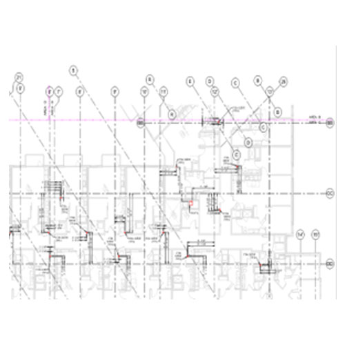
Penetration Drawing
Penetration drawings are created from the coordinated BIM model after alignment with the architectural grids and penetration drawings are required before a contractor can start pouring concrete on the site. Our experienced team keeps the necessary clearances for the penetration as per the contract documents and Specification.
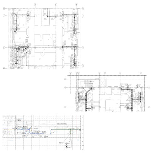
Shop Drawing
BIM is highly useful for contractors, fabricators, suppliers, and manufacturers during construction of any irregular or complex project to generate accurate shop drawings.
Utilizing a coordinated project BIM model, we generate accurate shop drawings that are detailed enough for workshop fabrication and/or on- site construction.
Shop Drawing produced with proper dimension, annotation, BOD, COP & BOP inline with client standard, sample and requirement as per standard practice.
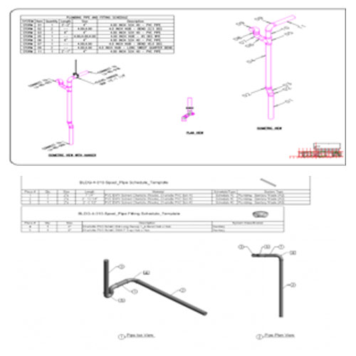
Spool Drawing
D & D produce the Spool drawings after the co-ordination of model. We design the spool template based on the standard practice for spool isometrics and material, accessories scheduling to complete the spool layouts. Our experience team is well trained to generate spool drawing as per standard practice and client requirements.
Hanger & Insert Drawing
D & D produce the Hanger & insert drawing with proper co-ordination of model and placing the hangers in line with specification. Hanger drawings shows the actual location of hangers with proper dimension from wall or grid. Insert are position of hangers insert points and D & D produce the proper insert drawing coordinating with actual hanger location in the model.
AS BUILT BIM
As Built Model & Drawing (LOD – 500)
After Installation of mechanical systems based on BIM drawings, Site team use to mark-ups the updates and changes in the plans based on the actual installation in site. Based on the site mark-ups, we create as built 3D model & drawing and prepare the as built set for project hand over and record.